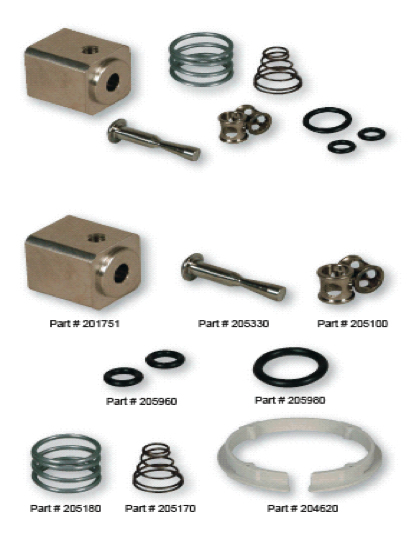
A machined part may appear ready for production, but even small dimensional variations can create significant challenges during assembly. Precision machining tolerances establish the acceptable range of variation from a specified dimension, helping ensure that individual components fit and function as intended. Understanding how tolerances are defined, what factors influence machining accuracy and how secondary operations affect final dimensions is essential to producing reliable, high-quality parts.
What Tolerance Really Means on a Drawing
A machining tolerance defines the acceptable range of variation around a nominal dimension, or the intended measurement specified on an engineering drawing. These limits help ensure that parts meet design requirements and fit properly within an assembly.
Tighter tolerances are typically specified for features where dimensional accuracy is critical, such as bearing bores, sealing surfaces and mating components. Achieving these requirements consistently requires the right combination of equipment, machining processes and quality controls.
How Tolerances Are Specified
Engineering drawings communicate tolerance requirements in several ways, most commonly through dimensional tolerances and geometric dimensioning and tolerancing (GD&T). Each approach serves a different purpose in defining the requirements for a finished part.
- Dimensional Tolerances
-
- Dimensional tolerances specify the acceptable variation in a particular measurement using plus and minus values
- Common examples include hole diameters, shaft lengths and wall thicknesses
- These tolerances are generally straightforward to interpret and can be verified using precision inspection instruments such as calipers and micrometers
- Dimensional tolerances specify the acceptable variation in a particular measurement using plus and minus values
-
- Geometric Dimensioning and Tolerancing
-
- Geometric dimensioning and tolerancing (GD&T) provides a more comprehensive way to define the allowable variation in a part’s geometry
- Rather than focusing solely on individual measurements, GD&T controls characteristics such as form, orientation, location and runout
- These controls help communicate how individual features must relate to one another to ensure proper fit and function
- In USA manufacturing, ASME Y14.5 is the primary standard used to interpret and apply GD&T requirements
- Geometric dimensioning and tolerancing (GD&T) provides a more comprehensive way to define the allowable variation in a part’s geometry
-
What Drives Achievable Tolerances
The ability to consistently achieve tight machining tolerances depends on several factors, extending beyond the capabilities of the machine itself.
Material selection plays an important role. Aluminum and brass generally machine cleanly and maintain dimensional stability, while certain stainless steel grades can work-harden during machining. These differences may require adjustments to cutting speeds, feeds and tooling to maintain accuracy and minimize material deflection.
Part geometry also influences achievable tolerances. Features such as thin walls, deep bores and long, unsupported sections can flex under cutting forces, making it more difficult to maintain precise dimensions.
Equipment condition and setup repeatability are equally important. Spindle accuracy, tool wear, fixturing and temperature fluctuations can all affect dimensional consistency throughout a production run.
Understanding these variables during the design process helps engineers identify which features require tight tolerances and where additional flexibility may be possible. This distinction can help control manufacturing costs without compromising the performance of the finished part.
Secondary Operations and Their Effect on Fit
Achieving the specified dimensions during primary machining is only part of the process. Secondary operations performed after milling or turning can also affect the final measurements of a component.
Plating, for example, adds a layer of material to the part’s surface. Depending on the coating thickness, this can increase external dimensions or reduce the clearance within bores and internally threaded features that were machined to size before plating.
Heat treating can also affect dimensional accuracy by introducing or relieving internal stresses, potentially causing slight changes in size or part geometry. The extent of these changes depends on the material and heat treatment process.
Other finishing processes, including deburring and abrasive blasting, remove small amounts of material and can alter dimensions, particularly along edges and corners.
Accounting for these potential changes during the initial design and manufacturing process helps ensure that the finished component meets its dimensional requirements after all operations are complete.
Send Your Drawing to Specialty Contract Mfg.
Understanding machining tolerances is an important part of designing a component that can be manufactured consistently and perform as intended. At Specialty Mfg. Co., we hold tolerances as close as .0002 inches on precision-machined parts made from aluminum, brass, stainless steel and other common materials.
Backed by ISO 9001:2015 certification and in-house engineering support, our team works with customers throughout the manufacturing process, from initial print review and design for manufacturability (DFM) considerations to secondary operations and final inspection.
Whether you’re developing a new component or refining an existing design, Specialty Contract Mfg. can help evaluate your requirements and identify the right manufacturing approach.
Send your drawing to Specialty Contract Mfg. for a DFM review.